
Bulk Material Handling
Two-Way vs Three-Way Diverter Valves for Multi-Line Dry Bulk Routing

Vijay Baid
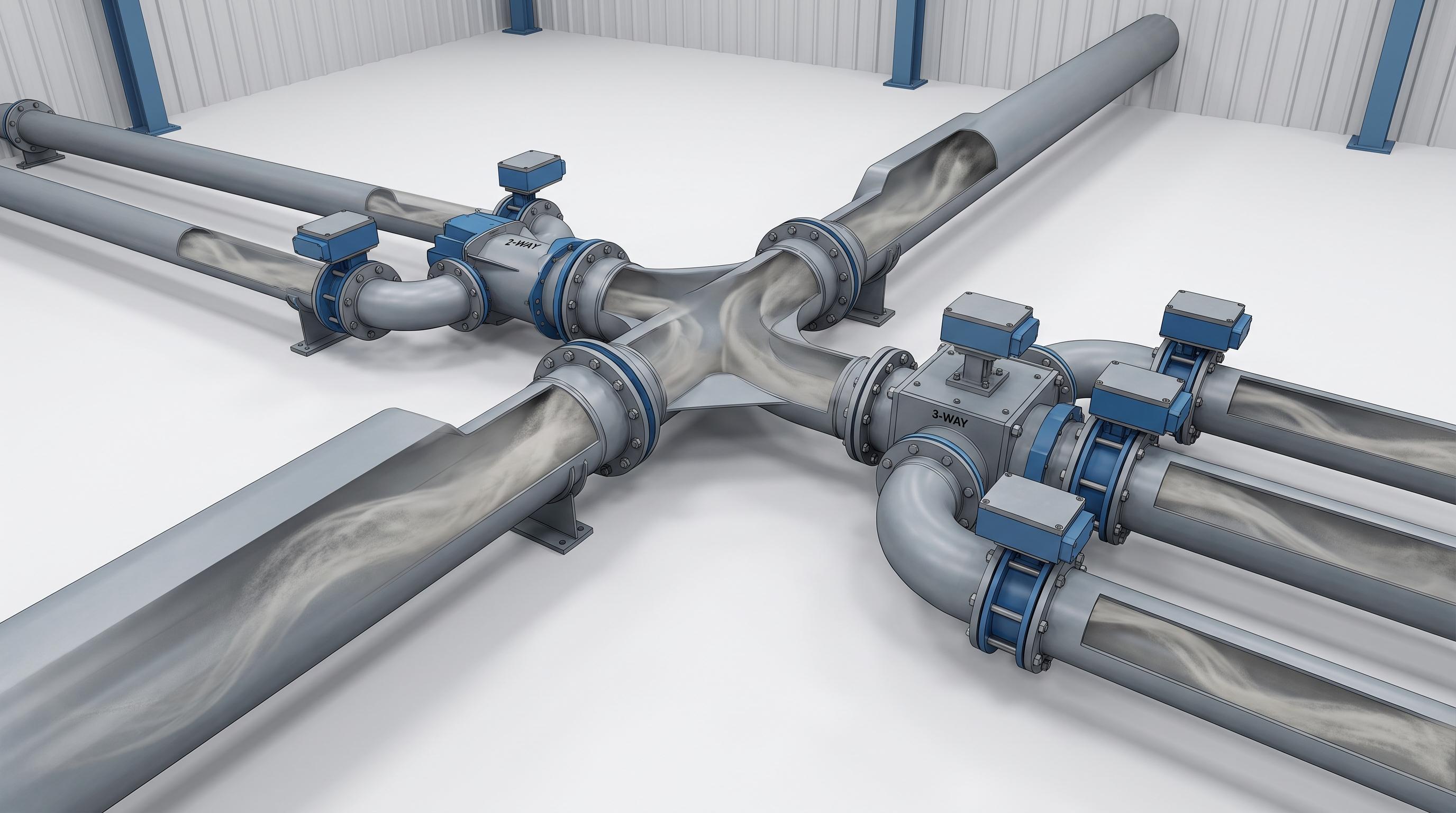
Choose a two-way diverter valve when material has to reach one of two destinations. Choose a three-way when a single valve has to feed three lines without adding parallel valves or extra piping. That part is simple. The harder question is whether the valve can hold a clean seal and survive your material. In abrasive, dusty dry bulk service, the number of outlets is rarely what causes trouble later.
This guide draws on the diverters United Global builds and services in cement, frac sand, and fly ash plants. It covers how each type works, when the third outlet is worth it, and the three factors that decide the right diverter for hard-running bulk materials.
A two-way diverter splits one inlet to two outlets. A three-way serves three destinations from a single body. Pick the outlet count from your plant layout, but pick the actual valve from pressure duty, material abrasiveness, and sealing needs. Size it to the line, line the wear zones with ceramic or hardened steel, and switch it only when the stream is empty.
Where two-way and three-way diverters part ways
A diverter valve sits at a junction in a conveying line and steers the material stream down one path at a time. The difference between the two families is only the number of paths, but that difference changes footprint, cost, and how many wear points you maintain.
A two-way diverter has one inlet and two outlets. It sends material to destination A or destination B, and nothing else. It is the straightforward answer for filling one of two silos, feeding a duty and a standby line, or routing product to a packer while keeping a maintenance bypass.
A three-way diverter feeds three destinations from a single inlet. Instead of stacking two separate valves and a run of extra pipe, one body and one actuator handle all three paths. That saves space and simplifies the header when a plant genuinely feeds three lines, blends from one source into three bins, or switches product families on the fly.
Factor | Two-way diverter | Three-way diverter |
|---|---|---|
Destinations from one inlet | 2 | 3 |
Typical use | Silo A or B, duty/standby, maintenance bypass | Parallel packers, multi-bin blending, product-family switching |
Footprint and piping | Compact, simple header | Replaces two valves plus interconnecting pipe |
Actuation and controls | One actuator, two positions | One actuator, three positions, more control logic |
Wear and maintenance points | Fewer sealing faces | More seats and transitions to inspect |
Relative installed cost | Lower per valve | Higher per valve, often lower per system |
Best fit | Simple, high-cycle two-way routing | Space-constrained plants feeding three real destinations |
How a two-way diverter moves material between two lines
Inside a two-way diverter, a moving element redirects the stream to the open outlet and closes the other. We build that element in several mechanisms so the valve matches the duty rather than forcing the duty to fit the valve. A pivoting blade or flap swings across the body for fast, clean two-way switching. A slide gate style plate works where a tight shut-off and a compact face matter. A rotating tunnel or plug carries the material path around inside a sealed body for pressure and dust control.
For gravity and low-pressure duty, a flap or blade is usually enough. For a line that has to hold a pressure boundary or keep dust contained, a tunnel or plug type with a full seal is the better base. The mechanism decides how the valve wears, how well it seals, and how fast it can cycle, so it deserves as much attention as the outlet count.
What a three-way diverter adds when a third destination comes in
The third outlet does more than add a path. It changes the internal geometry, adds a sealing face, and usually adds a control position. The mechanism then has to work harder to keep each path clean and leak-free. A well-built three-way diverter earns that complexity back by removing a second valve, a length of pipe, and a junction from the layout. Fewer joints in a header means fewer places for buildup, leakage, and misalignment to start.
Reach for a three-way when the plant truly feeds three destinations from one point. Common cases are a single source blending into three storage bins, one line serving three parallel packing machines, or a transfer point that has to route between three process trains. If two of the three paths are rarely used, two separate two-way valves may still be the more maintainable answer.
When two lines are enough, and when you really need three
The decision is a layout question first and a maintenance question second. Two-way is usually the better choice when the routing is genuinely binary. It also wins when the two destinations sit at convenient angles, or when high cycle frequency means you want the simplest mechanism to maintain. A single transfer chute and one two-way valve often beat a more complex arrangement.
A three-way earns its place when floor space or headroom is tight. It also fits where a plant would otherwise install two valves plus extra pipe to reach three bins. And it suits a fast product-family switch across three lines from one control point. If you find yourself specifying two diverters back to back to reach three outlets, a single three-way is usually cheaper to install and simpler to seal.
What actually decides the right diverter: pressure, material, and wear
Outlet count sorts diverters into two families. These three factors decide which specific valve survives in your plant. If you are comparing options for an upcoming project, this is the right point to pull the spec sheet and check line size, pressure duty, material, and sealing requirements against your routing layout.
Conveying pressure and phase
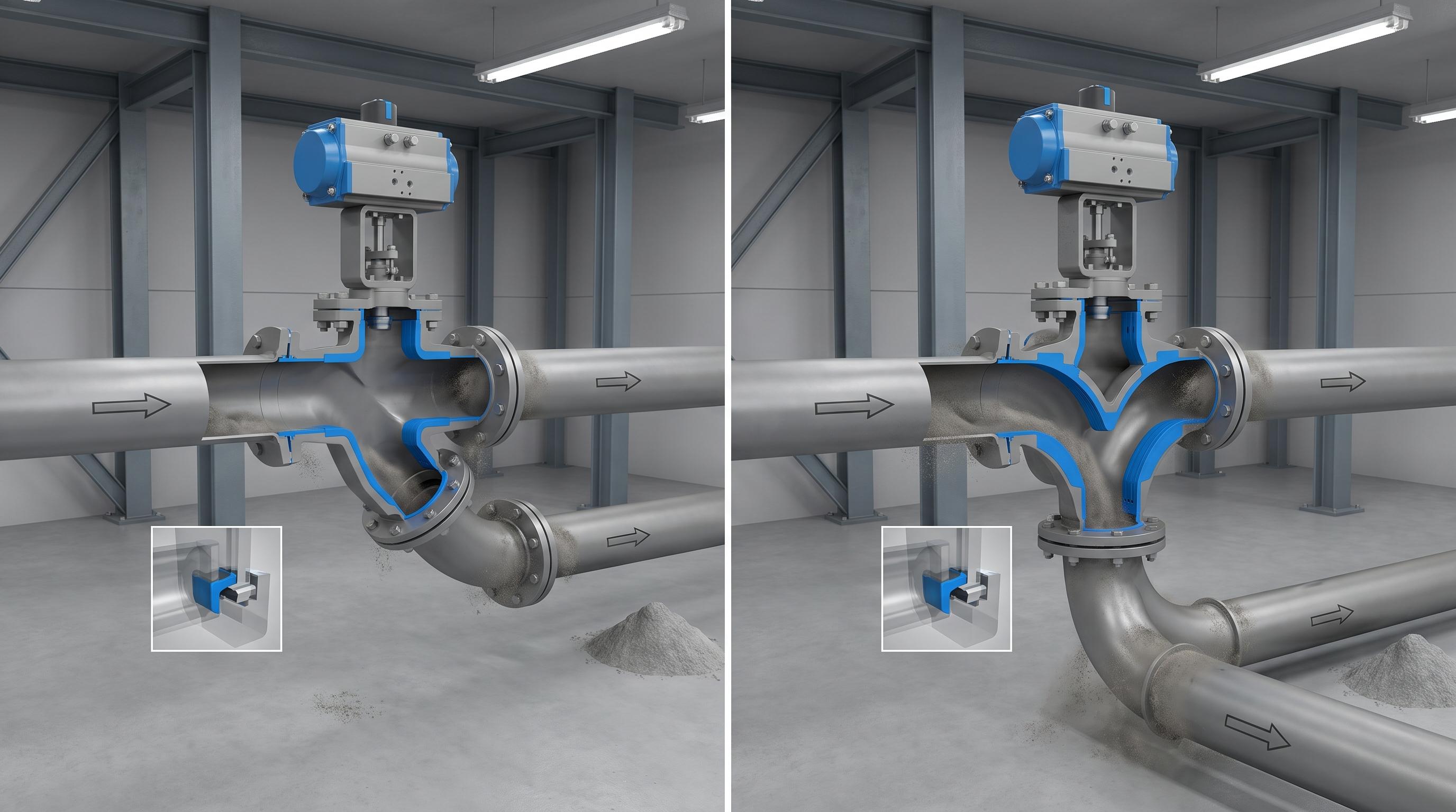
Match the valve to the line, not the other way around. A gravity or low-pressure chute can run a flap or blade diverter. A dilute or dense phase pneumatic line has to hold a pressure boundary, so it needs a full-seal tunnel or plug type with an air-tight seat. Dropping a gravity-grade diverter into a pressurized line is a common way to create leakage and unstable conveying. The same logic that governs a rotary airlock valve applies here. If the equipment has to maintain a pressure differential, it has to be built to seal, not just to switch.
Material and abrasion
Abrasive and heavy materials set the wear clock. Cement clinker, frac sand, fly ash, and crushed minerals cut into blades, seats, and transitions far faster than light powders. For that service, specify abrasion-resistant liners rated around 400 BHN, or ceramic lining in the highest-wear zones. That keeps the flow path in shape instead of letting it open into leak gaps as it wears. Sticky or hygroscopic materials pull the specification the other way, toward smooth transitions and non-stick faces that resist buildup.
Sealing and actuation
Sealing requirements often decide the valve on their own. A line that cannot tolerate cross-contamination between products needs a positive, air-tight seal on the closed leg, not a loose flap. Options run from air-tight rubber and PTFE seats to inflatable seals that clamp shut on demand. Actuation should match the cycle: pneumatic actuators for fast, frequent switching, electric or hydraulic where plant utilities favor them, and manual levers or handwheels for occasional routing changes.
Where multi-line routing tends to break down
Across the diverters we install and maintain, most problems trace back to a handful of repeatable mistakes rather than the valve itself:
Switching into a live stream. Diverting while material is flowing shears product across the blade or seat and accelerates wear.
Under-sealing a pressure line. A diverter that only steers, without a true seal, leaks air and product and destabilizes pneumatic flow. This is a frequent cause of diverter valve leakage and cross-contamination.
Ignoring abrasion until it leaks. Once the flow path wears open, the seal gap grows and dust escapes. Line the wear zones from the start.
Oversizing or undersizing. A valve that does not match the line diameter and capacity creates turbulence, buildup, and bounce at the junction.
Field rule: A diverter should switch only when the line is empty. Diverting into a live, flowing stream shears material across the blade or seat, and that is where leakage, cross-contamination, and premature wear usually begin.
What keeps a diverter working in abrasive, dusty service
In cement, aggregate, and frac sand plants, a diverter has to do more than route. It has to hold a seal against dust and stay compliant. Fugitive dust from a worn or leaking valve is both a housekeeping problem and a regulatory one. Respirable crystalline silica from sand and cement dust is regulated by the OSHA silica standard. The permissible exposure limit is 50 micrograms per cubic meter over an 8-hour shift, with an action level of 25. Combustible dusts such as certain grain, coal, and mineral fines fall under NFPA combustible dust standards like NFPA 652 and NFPA 654. Those standards require facilities to complete a Dust Hazard Analysis. Mine sites add MSHA requirements on top.
The practical answer is a valve that seals tight and resists wear. Air-tight or inflatable seats keep dust contained, abrasion-resistant and ceramic-lined flow paths hold their geometry, and guarded actuators keep the drive train inside OSHA machine-guarding rules. Conveying equipment specified to CEMA practice gives the rest of the line the same margin. A diverter that keeps its seal turns a routing junction from a dust source into a non-event. That is the same principle behind good dust control at transfer points across cement and mining plants.
How United Global builds diverters for multi-line plants
Across more than 500 installed systems in 15 industries, United Global manufactures both two-way and three-way diverter valves in the mechanism that fits the duty. Options include rotary and plug, slide and blade, flap, swing gate, pivoting chute, and drum. Bodies come in abrasion-resistant steel around 400 BHN, ceramic-lined, or stainless steel. Sizes run from 6 to 24 inches (150 to 600 mm), with custom sizing and a choice of pneumatic, electric, hydraulic, or manual actuation. Sealing options run from air-tight rubber and PTFE to gland packing and inflatable seals for lines that cannot tolerate leakage or cross-contamination.
That range matters because the right diverter for a power plant fly ash line is not the same as the right one for a food-grade product-switching header. Matching mechanism, liner, seal, and actuation to the material and the line is the difference between a valve that lasts and one that starts leaking within a season.
If you are selecting a diverter for a new line or trying to stop leakage, wear, or cross-contamination in an existing one, this is the point to review the actual duty. Sharing your line size, conveying pressure, material, throughput, and sealing requirement helps narrow the right mechanism, liner, and actuation before the problem turns into repeat maintenance.
Key takeaways
Two-way diverters route one inlet to two outlets. Three-way diverters serve three destinations from one body and one actuator.
Pick the outlet count from plant layout, but pick the actual valve from pressure duty, material abrasiveness, and sealing needs.
Pressure lines need a full-seal tunnel or plug type, not a bare flap.
Abrasive service such as cement, frac sand, and fly ash calls for 400 BHN or ceramic-lined flow paths to hold the seal as the valve wears.
Switch a diverter only when the line is empty, and seal the closed leg to prevent leakage, cross-contamination, and dust.
Frequently asked questions
Often yes, and it is usually the better choice when a plant truly feeds three destinations from one point. A single three-way body removes a second valve and a length of interconnecting pipe, which saves space and removes joints where buildup and leakage start. If one of the three paths is rarely used, two two-way valves can still be simpler to maintain.
Both, but the build has to match. Gravity and low-pressure lines can run a flap or blade diverter. Dilute and dense phase pneumatic lines have to hold a pressure boundary, so they need a full-seal tunnel or plug type with an air-tight seat. Using a gravity-grade valve on a pressurized line is a common cause of air leakage and unstable flow.
The blade, seat, and internal transitions take the most wear from abrasive materials like clinker, frac sand, and fly ash. Once the flow path wears open, the seal gap grows and dust escapes. Specifying abrasion-resistant liners around 400 BHN or ceramic lining in the high-wear zones holds the geometry and extends service life.
Match the valve to the line diameter, the conveying capacity in tons per hour, and the conveying pressure. Then account for the material's abrasiveness and bulk density. An undersized or oversized valve creates turbulence and buildup at the junction. Sharing your line size, material, and throughput lets our team size it correctly.
Per valve, a two-way costs less. Per system, a three-way is often cheaper when it replaces two valves plus interconnecting pipe to reach three destinations. Lifecycle cost then comes down to wear protection and sealing, because a valve that holds its seal avoids the repeated dust, cleanup, and downtime that drive the real cost.