
Carrying Idlers vs Return Idlers vs Impact Idlers: A Plant Engineer's Comparison Guide

Vijay Baid
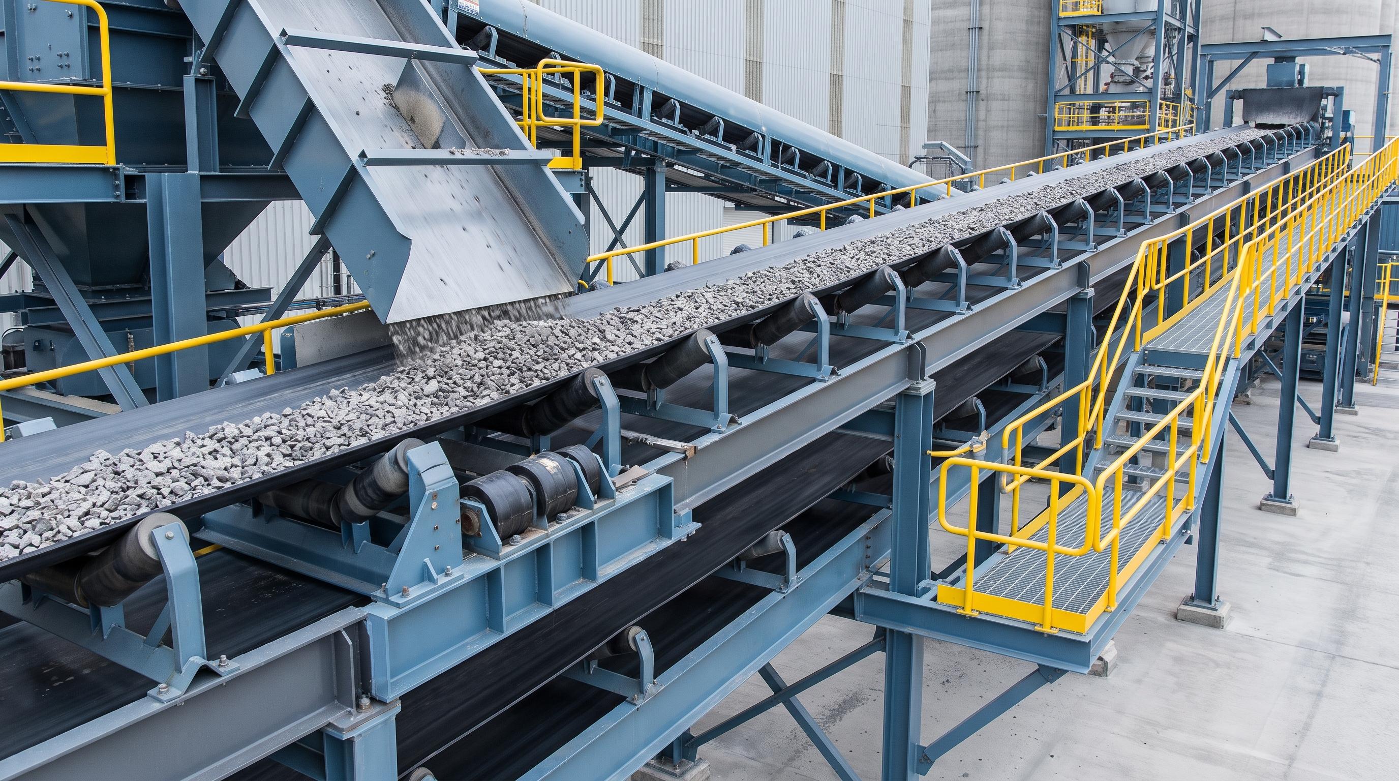
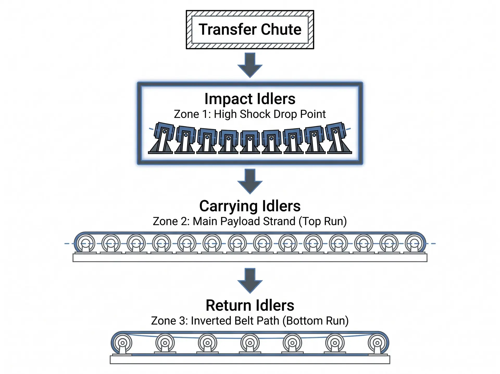
Carrying, return, and impact idlers are specialized mechanical supports engineered for distinct zones along a conveyor line. Carrying idlers shape and support the heavy payload on the top run; return idlers guide the empty, inverted belt on the lower run while managing carryback; and impact idlers absorb high-kinetic energy at loading transfer points to prevent belt carcass puncture.
In a perfect engineering world, raw bulk materials would flow across your plant's conveyors with zero friction, steady belt tracking, and zero dust. In reality, plant engineers in the cement, steel, and power sectors face a constant battle against premature roller wear, belt sagging, structural misalignment, and costly material spillage.
While the conveyor belt itself is often treated as the main driver of bulk material handling systems, its performance is directly dictated by the thousands of spinning idlers positioned beneath it.
Using the wrong roller type or the wrong spacing can damage the belt, overload the structure, and raise power use. To avoid that, plant engineers should understand the job of each roller type: carrying idlers, return idlers, and impact idlers.
Technical Comparison
Evaluation Metric | Carrying Idlers | Return Idlers | Impact Idlers |
Primary Conveyor Zone | Top loaded strand (carry run) | Bottom empty strand (return run) | Loading and transfer zone |
Mechanical Configuration | 3-roll troughed set | Single-roll flat return or V-return | 3-roll troughed set matching the carrying angle |
Typical Angle / Profile | 20° , 35° , or 45° trough | 0° flat or 10°–15° V-return | Same trough angle as the carrying set |
Standard Spacing | 1.0–1.5 m (3.0–5.0 ft) | 3.0 m (10.0 ft) | 300–450 mm (1.0–1.5 ft) |
Main Engineering Duty | Support and shape the loaded belt | Support belt return and maintain tracking | Absorb impact energy at loading points |
Design Priority | Load capacity and low roll resistance | Belt tracking and carryback control | Shock absorption and belt protection |
1. Carrying Idlers: Shaping the Payload
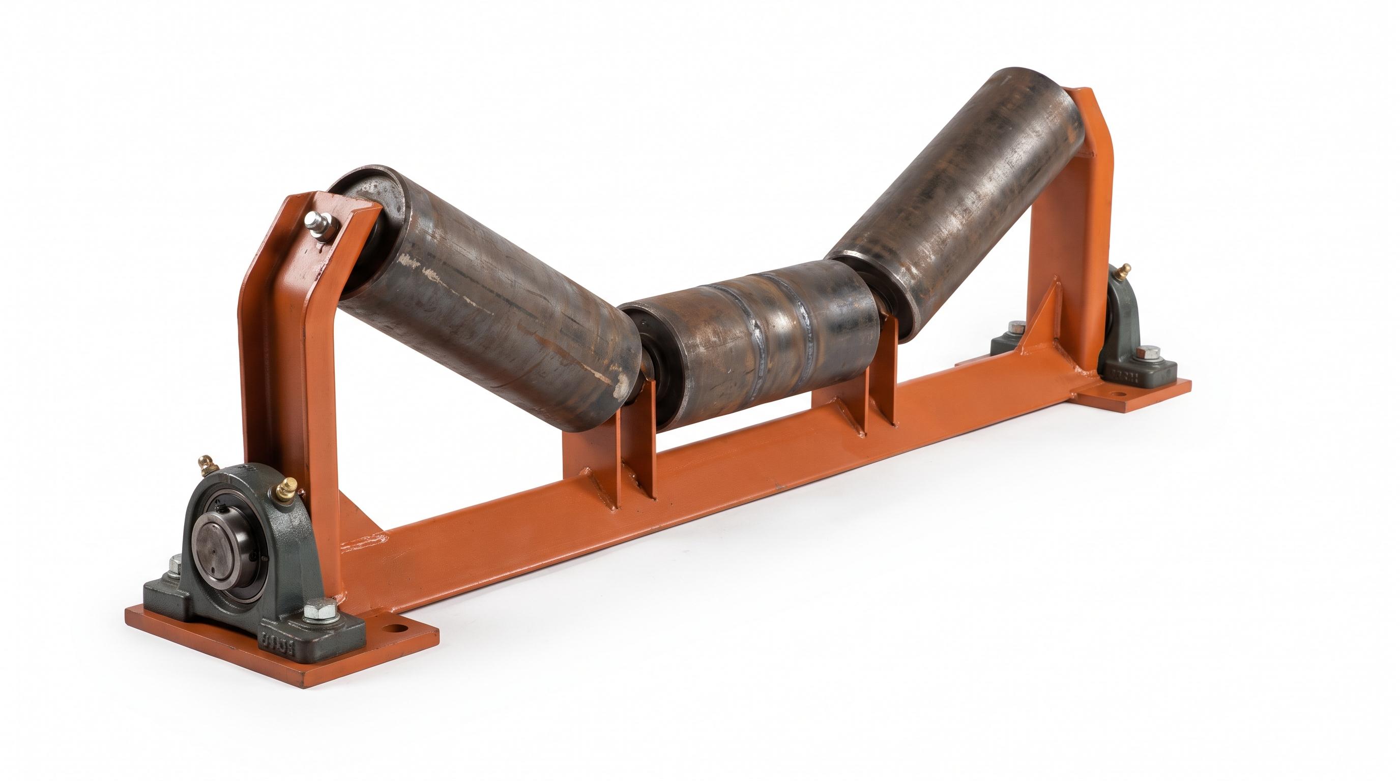
Carrying idlers are installed along the top run of the conveyor line. They feature a multi-roll design most commonly a three-roll configuration mounted on a rigid structural steel frame to shape the belt into a trough. For Indian standards research on conveyor components and related specifications, see the Bureau of Indian Standards (BIS) reference portal.
Key Technical Specifications
Location: Top carrying strand from the tail loading transition to the head Conveyor Pulley transition.
Construction: Three equal-length steel rollers using ERW steel tubing, solid cold-drawn steel shafts, and welded end housings.
Working Principle: The outer wing rolls are angled at 20° , 35° , or 45° . This forces the flexible rubber belt into a deep trough, maximizing the cross-sectional area of the bulk material and preventing spillage during high-speed transit.
Advantages & Limitations
Advantages:
Maximizes bulk material carrying capacity per linear meter.
Holds the belt in a rigid cross-sectional shape to stabilize material movement.
Evenly distributes material weight across three independent bearings.
Limitations:
Cannot absorb severe vertical shock impacts.
Rigid steel shells will dent or crack if subjected to heavy lump drops from chutes.
Failure Modes & Maintenance Requirements
Bearing Seizure: Fine abrasive dust entering the housing locks the internal bearings, causing the roller shell to freeze.
Shell Grooving: A frozen roller drags against the moving belt, rapidly grinding the steel tube down into razor-sharp edges that tear the belt cover.
Maintenance Focus: Conduct thermal imaging to identify seized bearings and inspect shell wall thickness during scheduled maintenance outages.
2. Return Idlers (Path & Alignment Supporters)
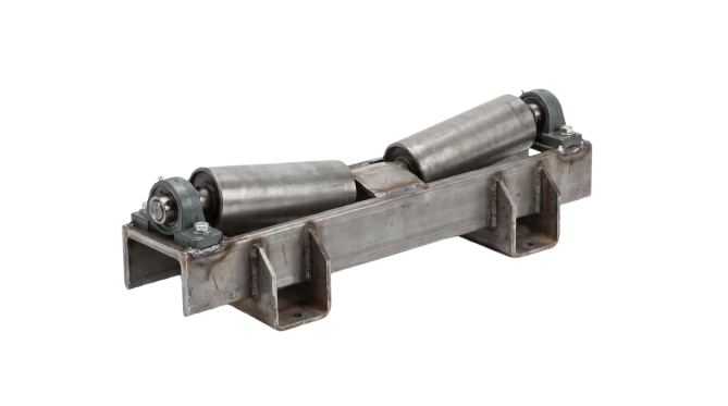
Return idlers support the empty belt on its inverted journey back from the discharge head pulley to the tail pulley.
Key Technical Specifications
Location: Bottom return strand along the underside of the conveyor frame.
Construction: Single long steel roller (Flat Return) or a central steel tube fitted with spaced, resilient rubber or polyurethane discs.
Working Principle: Supports the dead weight of the empty return belt across wide spans. Rubber disc variants flex under belt tension, cracking and shearing off wet or sticky material carryback that bypasses primary belt scrapers.
Advantages & Limitations
Advantages:
Simple, low-cost structural profile.
Rubber disc and spiral variants actively shed carryback, preventing buildup.
V-return profiles (10° to 15°) provide natural passive belt centering.
Limitations:
High vulnerability to shell eccentricity caused by material crust buildup.
Wide span spacing makes the return belt prone to lateral wind drift.
Failure Modes & Maintenance Requirements
Scale Buildup & Belt Mistracking: Sticky fines compress onto the steel shell, artificially enlarging the roller diameter in uneven spots and forcing the belt off-center.
Ring Debonding: Heavy abrasion or chemical exposure can cause rubber discs to split and detach from the steel core.
Maintenance Focus: Clean accumulated carryback from return frames and inspect rubber discs for wear patterns.
3. Impact Idlers (The Shock Absorbers)
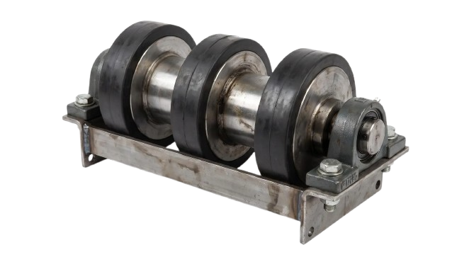
Impact idlers are specialized structural sets installed directly inside material loading points and transfer chutes where raw materials drop onto the conveyor, often fed upstream by Rotary Airlock Valves. For mining-sector safety requirements and statutory guidance around material-handling risk, refer to the Directorate General of Mines Safety (DGMS).
Key Technical Specifications
Location: Material feed drop zones, loading chute skirts, and crusher discharge points.
Construction: Reinforced structural steel frame supporting rolls wrapped in thick, high-resilience vulcanized rubber or polyurethane rings.
Working Principle: Positioned closely together (300 mm to 450 mm spacing), the resilient elastomeric rings deflect under heavy material impact. This compresses the kinetic energy of falling rocks, preventing the belt carcass from being pinched and crushed against a solid steel surface.
Advantages & Limitations
Advantages:
Prevents micro-punctures, longitudinal tears, and fiber damage in the belt carcass.
Absorbs shock energy to protect structural chute frameworks and bearing assemblies.
Maintains a continuous trough angle directly below the loading skirt to reduce spillage.
Limitations:
Higher rotational resistance increases drive motor drag.
Rubber rings can degrade when exposed to continuous high temperatures (e.g., hot sinter clinker above 120°).
Failure Modes & Maintenance Requirements
Elastomer Thermal Degradation: Excessive heat or chemical exposure softens or cracks the rubber rings.
Frame Deformation: Severe over-capacity lump drops can bend the mounting feet if structural ratings are exceeded.
Maintenance Focus: Check ring compression gaps and inspect lock-rings to ensure shock rings do not shift laterally along the tube.
Need Complete Technical Specifications for Engineering Reviews or Procurement? Download our complete idler spec sheet to compare dimensional tolerances, shell wall thicknesses, and load profiles across carrying, return, and impact configurations.
"Wrong Idler in Wrong Location" Scenarios
Deploying the wrong idler type in a conveyor zone causes structural damage, excessive material spillage, and unscheduled shutdowns.
Scenario 1: Standard Steel Carrying Idlers Under a Primary Drop Chute
The Mistake: Installing standard steel troughing rollers directly under a loading chute receiving 150 mm limestone lumps falling from a height of 3 meters.
The Result: The unyielding shock deforms the thin steel tube shells and shatters the internal ball bearings within weeks. The crushed steel shell develops sharp, jagged edges that slice continuous grooves into the bottom cover of the moving belt.
The Correct Specification: Replace the first 4 to 6 steel frames with heavy-duty Impact Idlers placed at close 300 mm intervals.
Scenario 2: Standard Flat Steel Return Idlers on Sticky Wet Coal Lines
The Mistake: Using smooth, flat steel return rollers on a coal reclaim line where moist fines bypass the head scraper.
The Result: Fine coal carryback builds up on the smooth steel shell, forming an irregular, hardened crust. This crust changes the effective diameter of the roller, causing severe belt mistracking and cutting into the conveyor stringers.
The Correct Specification: Swap flat steel rollers for Rubber Disc Return Idlers or Spiral Cleaning Idlers to break up material scale.
Scenario 3: Impact Idlers Placed Along the Main Carrying Strand
The Mistake: Over-specifying impact idlers along the entire carry run to "maximize durability."
The Result: The rubber rings create significantly higher rolling resistance compared to smooth steel shells. This increases drive motor amperage draw, increases power consumption, and accelerates surface wear on the bottom cover of the belt.
The Correct Specification: Restrict impact idlers strictly to material drop zones, using smooth, heavy-wall Carrying Idlers along the main run.
Real Plant Examples
Cement Clinker Lines: Plants pairing deep 45° carrying idlers on top with rubber disc return idlers on the bottom successfully prevent fine abrasive clinker dust from baking onto flat steel shells.
High-Speed Coal Transfer: Coal handling circuits using closely spaced (300 mm impact idlers under drop chutes alongside standard 35°carrying idlers on the main run eliminate drop-point belt carcass punctures while maintaining high-speed payload capacity.
Common Design and Installation Mistakes
Even high-quality idlers will fail early if installed incorrectly. For formal standards checks and safety reviews, cross-reference equipment choices with BIS specifications and applicable DGMS safety guidance before finalizing the layout.
Inadequate Impact Support: Installing standard steel carrying rollers under feed chutes is a common design error. The constant pounding of falling material easily deforms steel shells and destroys internal bearings. Always use dedicated impact idlers or an impact cradle below discharge chutes.
Incorrect Spacing in Transition Zones: Transition zones where the belt flattens out to wrap around a pulley experience intense edge tension. Spacing standard troughing idlers too close to the head or tail pulley stretches and damages the belt edges. Use specialized, adjustable transition idlers to ease the belt from flat to its full trough angle.
Ignoring Return Path Cleanup: Wet or sticky materials can bypass the primary belt scraper, leaving a thin film on the return side of the belt. If standard steel return rollers are used, this carryback builds up on the steel shells, causing severe belt mistracking. For sticky materials, always install rubber disc or spiral cleaning return idlers to break up and remove carryback.
Need Help Troubleshooting Misalignment, Belt Wear, or Spillage Points?
Our engineering team can evaluate your conveyor layout, inspect your drop zones, and specify the correct idler configurations for your plant.
From the field: At a thermal power plant, the maintenance team was replacing return idlers every month on a high-speed coal conveyor. The 1,200 mm belt was running at 3.8 m/s on older CEMA C rollers. Fine coal dust got past the simple seals and mixed with the bearing grease. Several rollers seized. The moving belt then dragged over the frozen steel shells and wore them sharp. Those sharp edges started cutting grooves into the lower belt cover. The line was close to a major belt failure. We solved the problem by upgrading to CEMA D idlers with triple-labyrinth grease seals and 152 mm rolls. The larger rolls reduced RPM. The better seals kept dust out. After the change, bearing failures stopped, and the conveyor ran for more than two years without an unscheduled shutdown.
Final Key Takeaways
Geometry & Placement Contrasts: Carrying idlers use multi-roll troughed geometries (20°– 45°) along the top run; return idlers use flat or shallow V-profiles (0°–15°) on the bottom run; impact idlers mirror carrying trough angles but are strictly restricted to transfer chute drop zones.
Load & Shell Material Differences: Carrying idlers feature smooth, rigid steel or composite shells engineered for continuous static payload weight; impact idlers use thick, resilient rubber or polyurethane discs to absorb kinetic shock; return idlers utilize single smooth tubes or spaced rubber discs to manage carryback friction.
Spacing & Mechanical Profile Differences: Impact idlers are installed at ultra-close intervals (0.3 m – 0.45 m) to eliminate belt sag under chute drops; carrying idlers are spaced at standard spans (1.0 m –1.5 m); return idlers span wide distances (3.0 m) across the empty belt run.
Frequently Asked Questions (FAQ)
The main differences are load capacity, roll shaft diameter, and bearing size. CEMA D idlers have heavier frames, thicker shafts, larger bearings, and larger roll diameters (127 mm to 152 mm) than CEMA C models. This design allows them to handle larger bulk loads and higher belt speeds.
Yes, but only in the transition zones near the head and tail pulleys. Transitioning directly from flat to a 35o or 45o angle stretches and damages the belt edges. Using transition idlers with intermediate angles (such as 10o and 20o) safely steps the belt down to flat.
Moist, sticky material that escapes the head pulley scrapers can build up on steel return rollers. Rubber disc idlers feature spaced rubber rings that flex as the belt passes. This flexing action breaks up the material crust, preventing it from sticking to the roller.
If a roller's bearings seize due to dirt contamination or grease loss, the roller stops spinning. The moving conveyor belt continues to slide across the frozen roller, quickly grinding down the steel shell until it wears flat.
For long conveyors, self-aligning idlers should be spaced every 30 to 45 meters along the carry and return runs. You should also position a trainer approximately
15 meters before the head and tail pulleys to ensure the belt enters the pulleys centered.