
Engineering Guides
Pneumatic Conveying System Components: Complete Design & Selection Guide

Vijay Baid
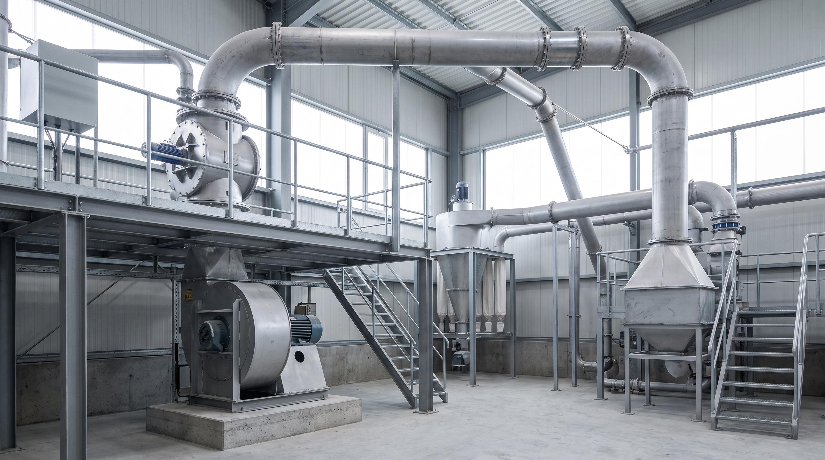
A pneumatic conveying system only works as well as its weakest component. Most failures start when the air mover, feed device, line size, bend layout, and receiver are selected in isolation instead of as one pressure-balanced system. The fast engineering takeaway is simple: size the system from the material backward bulk density, particle size, moisture, abrasiveness, temperature, route, and duty cycle must decide the component package, not the other way around.
Pneumatic conveying looks clean on a flow diagram, but plant performance is won or lost in the details. A line that is easy to draw can still plug, wear through elbows, flood a filter, or starve a downstream process if the components are mismatched. That is why two systems with the same pipe diameter can behave very differently on the shop floor.
For plant teams, the pain shows up fast: unstable feed, higher blower load, dust escape at transfer points, repeated line choking, and maintenance work that never seems to end. The good news is that most of these problems are traceable. Once you understand what each component is supposed to do, selection becomes much more disciplined.
How a pneumatic conveying system actually works
A pneumatic conveying system moves bulk solids by using air pressure or vacuum to carry particles through a closed pipeline. In practical terms, one component creates airflow, another meters solids into that airflow, the pipeline transports the mixture, and the receiver separates product from air before the clean air is discharged or recirculated.
The design target is not just “move material from A to B.” The real target is to move it at the required rate, with stable feed, acceptable wear, limited degradation, safe dust control, and reasonable power draw. If one of those conditions is missed, the system may still run, but it will not run well.
Three simple equations keep the early design honest:
Air velocity: V = Q / A, where V is conveying velocity, Q is volumetric airflow, and A is pipe cross-sectional area.
Solids loading ratio: ms / ma, where ms is solids mass flow and ma is air mass flow.
Total pressure drop: ΔPtotal = ΔPpickup + ΔPstraight pipe + ΔPbends + ΔPreceiver/filter + margin.
These are not academic formulas. They tell you whether the air mover has enough duty, whether the line is likely to salt out, and whether the receiver will become the hidden bottleneck.
The components that decide system performance
The right component package starts with duty, not catalog size. Each item below has one core job, and problems start the moment it is asked to do a different one.
1) Air mover: blower, fan, or compressor
The air mover sets the pressure and airflow available to transport the solids. In most industrial systems, the common choices are Roots blowers, centrifugal blowers, and screw compressors.
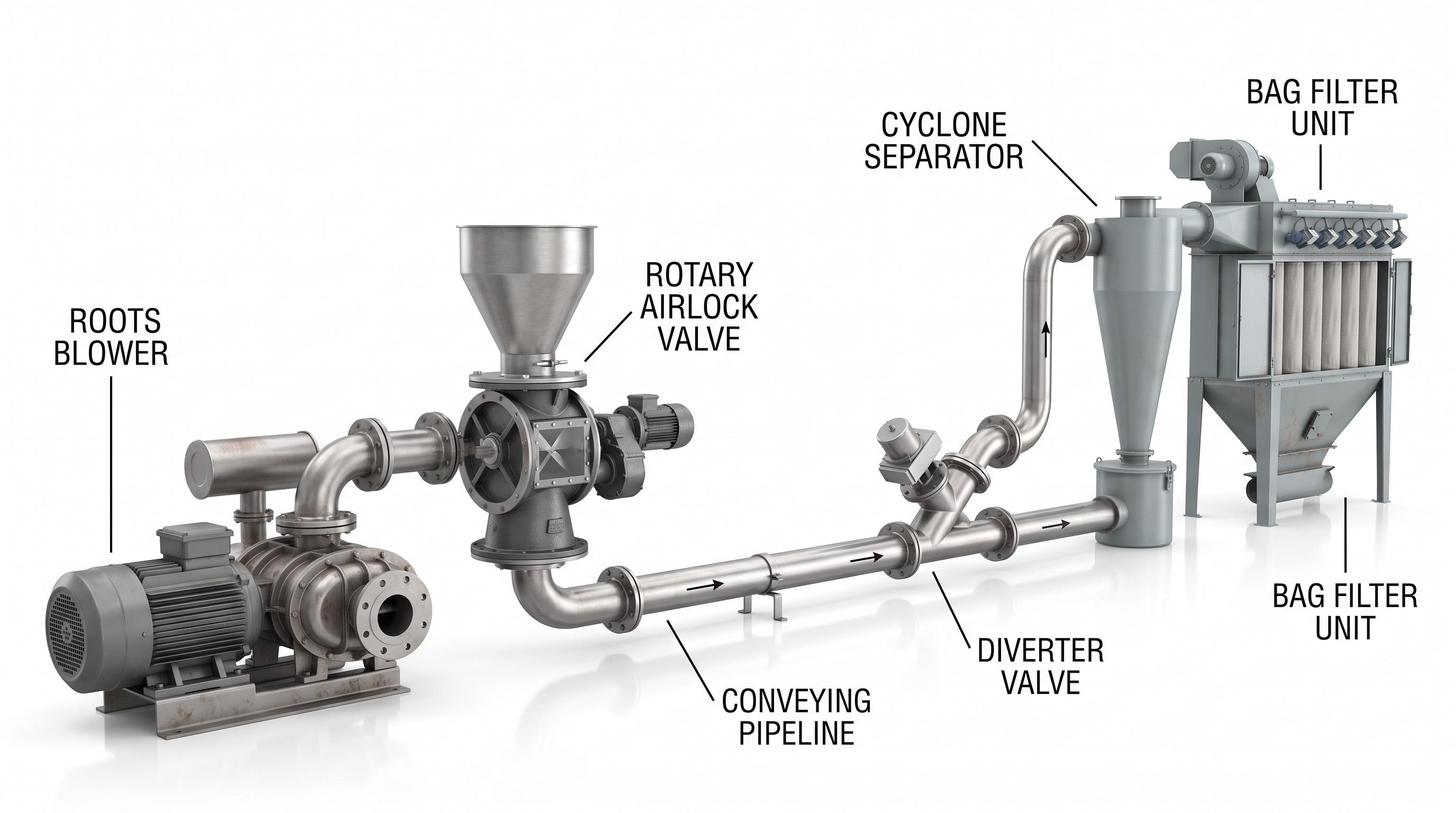
Roots blowers are common in dilute-phase duty because they deliver steady airflow over a practical pressure range and tolerate plant conditions well. They are simple, proven, and easy for maintenance teams to understand. Their weakness is efficiency at the wrong duty point.
Centrifugal blowers fit high-airflow, lower-pressure duties. They can be a good choice where the line is long but pressure demand is modest. They are less forgiving if the system curve shifts far from design.
Screw compressors are used where higher pressure and tighter control are needed, especially in denser-phase applications. They usually cost more up front, but they can stabilize difficult duty where a lower-pressure machine cannot hold the line.
2) Feed device: rotary airlock, rotary feeder, or pressure vessel
The feed device introduces material into the airstream without destroying the pressure balance. This is where many systems fail, because the feed device is often chosen by habit.
A rotary airlock valve and rotary feeder do not solve the same problem. If the duty needs pressure sealing, the airlock matters. If the duty needs only metering, a feeder may be enough. Using the wrong one causes blowback, unstable pickup, dusting, and line starvation.
For systems that feed directly into a pressure line, the airlock type itself also matters. Blow-through duty, drop-through discharge, friable material, and low headroom each point to a different mechanical answer.
3) Pipeline and bends
The pipeline is not just a transport path. It is the pressure-loss network that the whole system must overcome. Pipe diameter, length, vertical lift, bend radius, and the number of directional changes all decide whether the selected airflow is enough.
Straight pipe adds predictable friction loss. Bends are where the system usually gets expensive. They increase pressure drop, accelerate wear, and in abrasive service they become the first place a line fails. Short-radius bends are compact, but they punish both product and pipe. Long-radius bends or wear-back elbows cost more, yet they often save money over the life of the line.
4) Diverter valves and routing components
Diverter valves decide where the product goes after it enters the line. In multi-destination systems, they must switch cleanly, seal well, and avoid dead pockets where material can build up. For routing layouts, two-way and three-way diverter selection should be matched to the actual number of destinations and switching duty.
Fine powders need a tighter-sealing diverter than coarse granules. Abrasive duty needs wear-resistant internals. High-cycle duty needs an actuator package that can switch repeatedly without hammering the seats. If routing is frequent, this is not a minor accessory. It becomes a reliability-critical component.
5) Separation and filtration equipment
The receiver must separate product from conveying air without becoming the system choke point. A cyclone can remove coarse product and reduce filter loading. A bag filter or cartridge filter handles fine dust that the cyclone misses. In many plant systems, the right answer is not cyclone or filter. It is cyclone plus filter, sized as a pair.
When the receiver is undersized, air velocity climbs inside the vessel, fines carry over, bags blind faster, and the system pressure creeps up. The line then behaves like a transport problem even though the real problem is poor separation duty.
Before you compare quotes, lock the baseline: throughput, material, route, pressure, wear points, and access. A clear spec sheet keeps engineering, procurement, and maintenance aligned and helps prevent a bad fit.
Technical Comparison
Option | Best fit | CapEx | OpEx | Maintenance | Typical failure mode |
|---|---|---|---|---|---|
Roots blower | General dilute-phase plant duty | Medium | Medium | Low to medium | Overheating or unstable duty when pressure demand exceeds design window |
Centrifugal blower | Higher airflow, lower-pressure systems | Medium | Low to medium | Low | Duty drift and loss of usable pressure margin |
Screw compressor | Higher-pressure or dense-phase duty | High | Medium | Medium | High running cost if used where lower-pressure equipment would do |
Drop-through rotary airlock | Gravity-fed discharge into controlled line entry | Medium | Low | Medium | Air leakage after clearance growth or product bridging below the valve |
Blow-through rotary airlock | Direct feed into pressure line | Medium to high | Low | Medium | Pocket wear, leakage, and unstable feed into the line |
Plug or flap diverter valve | Two-way or multi-line routing | Medium | Low | Medium | Seat wear, cross-contamination, or jamming at changeover |
Cyclone + bag filter | Fine powder recovery with dust control | High | Medium | Medium to high | Filter blinding, carryover, or excessive pressure drop across bags |
Selection factors and design considerations
The correct component selection starts with the material. If the material is abrasive, you design for wear first. If it is friable, you design for low velocity first. If it is moist or sticky, you design to prevent buildup first. The line route comes after that.
Bulk density: Low-density material needs more volumetric capacity for the same tonnage. That affects feed device size, pipe loading, and receiver sizing.
Particle size and shape: Fine powders suspend easily but can flood filters. Coarse particles need more pickup energy and hit bends harder.
Moisture: Moisture raises the risk of wall buildup, line choking, and airlock packing. A material that handles well in the dry season may become unstable during monsoon conditions.
Abrasiveness: High-silica or ash-rich material needs hardened elbows, airlock tips, and wear-liner planning from day one.
Temperature: Hot product affects clearances, seal materials, and receiver filter media.
Duty cycle: A line that runs once per shift can tolerate more compromise than one that runs continuously.
Environment: Outdoor lines, corrosive dust, and explosive atmospheres all change the component package.
Safety has to be engineered into the same selection process. For combustible or hazardous dusts, the system has to be checked against OSHA combustible dust guidance, NFPA 660, and machine-risk principles such as ISO 12100. In other words, component selection is not only about flow. It is also about safe failure behavior.
What fails if the design is wrong
The most expensive pneumatic conveying failures are usually slow failures. They begin as a small mismatch, then show up as maintenance noise before they become downtime.
Undersized air mover: The line works when empty, then salts out under full load.
Oversized airflow: Product breaks down, bend wear rises, and the filter sees too much fine dust.
Poor airlock selection: Pressure leaks backward, pickup becomes unstable, and feed rate hunts.
Tight bend layout: Pressure drop rises and elbows wear much faster than planned.
Receiver too small: The system looks like a pipeline problem, but the real issue is carryover and filter overload.
No allowance for duty cycle: Bearings, seals, and flexible connectors fail early because the equipment was sized for capacity but not for runtime.
If you are working around unstable feed, elbow wear, repeated plugging, or uncertain component sizing, a full-duty review is usually faster than another trial-and-error replacement
Field experience: One failure pattern we see on site is a line that runs acceptably at startup, then becomes unstable after a few months. Operators start reporting surging feed, the blower sounds loaded, and housekeeping around the inlet gets worse. On paper, the installed equipment still matches the original capacity. In the plant, the line is no longer doing the same job.
The usual cause is not one dramatic break. It is a chain reaction. Airlock clearances open from wear, the pipe sees more backward air leakage, the pickup point loses stability, and the operator compensates by pushing more air. That extra air raises velocity through the bends and receiver, which creates more fines, more pressure loss, and more filter loading. The line becomes harder to run every week.
The correction is normally straightforward once the root cause is seen clearly: restore feed sealing, rebalance the air-to-solids ratio, check bend condition, and verify the receiver pressure loss under real operating load. When those four items are corrected together, the line stops behaving like a blockage problem and starts behaving like a designed system again.
Final Takeaway
The rule is simple: do not choose a pneumatic conveying component on capacity alone. Start with the material first bulk density, particle size, moisture, abrasiveness, and temperature decide what the system can handle. Then check the route, including line length, bends, vertical lift, and total pressure loss. Only after that should you size the blower, feed device, pipeline, and receiver. In pneumatic conveying, reliable performance comes from keeping airflow, feed rate, and pressure loss in balance.
Frequently Asked questions(FAQ)
No single air mover is best for every duty. Roots blowers fit many dilute-phase systems, centrifugal blowers suit higher-airflow lower-pressure duty, and screw compressors fit higher-pressure or denser-phase service. The correct choice depends on required airflow, total pressure drop, control range, and runtime.
Choose a rotary airlock when the duty must maintain a pressure boundary while feeding solids. Choose a feeder when the duty mainly needs metering under near-atmospheric conditions. If pressure sealing is ignored, the line will lose stability quickly.
Bends force particles to change direction at speed, which raises impact energy and local wear. The sharper the bend and the more abrasive the material, the faster the wear. That is why bend radius and material choice matter so much in system life.
Use a blow-through airlock when solids must be fed directly into a pressure line and the system benefits from a compact entry arrangement. It is common in pneumatic conveying duty where a separate dropout section would create buildup or layout problems.
Often, yes. A cyclone removes the heavier product load and reduces the burden on the bag filter. The bag filter then captures the finer dust that remains in the air stream. Using both can improve recovery and reduce filter stress in fine-powder duty.
The most common cause is not one single fault. Plugging usually comes from a combination of unstable feed, low effective air velocity at pickup, excessive moisture, or pressure loss that was underestimated during design. Stable conveying depends on getting all four under control.